 |
> E&O/GL Insurance for Home Inspectors Competitive Rates, Broad Coverage, Free Risk Management, online inspection support for tough questions, discounts on education and more… Professional Coverage, Competitive Pricing Shop OREP today! |
Hydronic Boilers Through Time – The Science Behind Your Inspection
by Tom Feiza, Mr.Fix-It, Inc., HowToOperateYourHome.com
Residential hydronic boilers have been around for a long time. The first central heating systems in “modern” 1850s mansions were gravity hydronic or gravity warm air. (Prior to that, homes were poorly heated with wood, coal or gas fireplaces, Franklin stoves and kitchen stoves/wood burners.)
We often see components of those old hydronic systems during home inspections. And unless we specialize in old homes, we don’t understand those crazy leftover parts: hydronic heating pipes reduced from six inches to one inch diameter, multiple access doors and openings for large ducts installed through basement walls. Why would they do that?
Let’s Look at Old Gravity Hydronic Boiler Systems
Although we call gravity hydronic heating systems “boilers,” they don’t boil water. Steam systems boiled water; they are another type of central heating which was popular in the old days. But for now, let’s focus on gravity hydronic systems in which water was heated until it rose through the piping to radiators, and then cooler water dropped to the boiler.
To make sense of old components we see during inspections, we need to understand the old gravity hydronic heating system (See Figure 1: Gravity-Type Hydronic Boiler), with its large pipes, manual water make-up, radiators, multiple boiler access doors and an expansion tank in the attic.
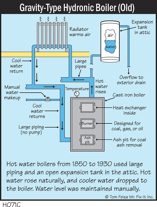
Figure 1: Gravity-Type Hydronic Boiler
Look at an actual system (See Figure 2: Old Gravity Hydronic Boiler). Note the oversized circulating pipes. They needed to be so big because the system had no pump. Water flowed naturally in this system: hot water rose, and cold water dropped. (We will ignore the asbestos pipe wrap in this instance.)
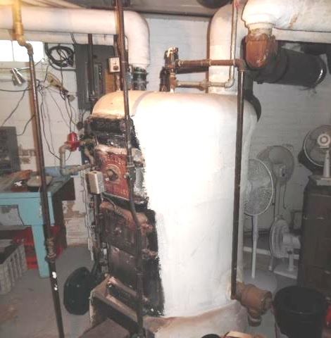
Figure 2: Old Gravity Hydronic Boiler
In later years, such systems began to incorporate Bell & Gossett brand pumps (See Figure 3: Hydronic Boiler Circulating Systems). The classic red B&G pumps had a mechanical coupler from the motor to the sealed impeller shaft. The couplers could get noisy, and the pump and bearings needed a few drops of oil twice per year. In general, the pumps lasted forever, but the seals could leak and overzealous oiling could damage the rubber mounting blocks.
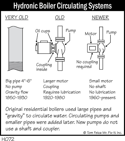
Figure 3: Hydronic Boiler Circulating Systems
Gravity moves water slowly, so large pipes were required. When we add a pump to the system, the water and energy can move quickly through the system and the pipes can be quite small. (See Figure 4: Hydronic Large To Small Piping). When gravity systems are converted to a newer boiler with a pump, the large pipes are connected to the new, smaller pipes.
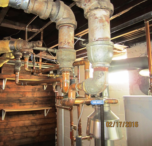
Figure 3: Hydronic Large to Small Piping
Compare the photo of the old gravity hydronic boiler with another system (Figure 1), which has very large pipes and no pump. This old boiler has multiple access doors that allow the operator to fire the boiler with coal and remove the clinkers. This boiler could have been fired with coal, oil or gas. It has been converted to a gas burner.
(story continues below)
How Was Indoor Temperature Controlled?
A duct damper was often used on the air supply and/or flue pipe to the coal combustion in an old gravity boiler (See Figure 5: Air Supply Duct Damper). The combustion air supply duct was routed outside the building though the basement wall with a 12- to 14-inch vent connector. We now see these vent connectors closed and covered (See Figure 6: Duct Through Basement Wall). People often guess that this is a remnant of a coal chute, but more likely it was the combustion air supply to a coal burner.
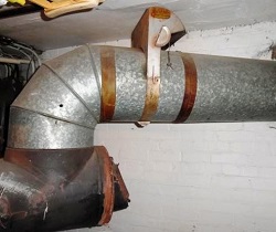
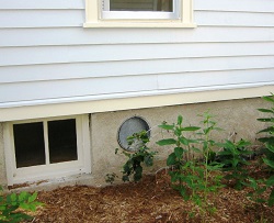
From left to right: Figure 5: Air Supply Duct Damper; Figure 6: Duct in Basement Wall
Interior temperature was controlled by a mechanical thermostat (See Figure 7: Gravity Heat Control). Well, OK, it’s not really a thermostat, because it didn’t sense interior temperature. It was a small dial, generally on the interior wall baseboard. Thin chains connected the dial to the duct damper(s) in the basement (See Figure 8: Air Supply, Cole Draft Governor). Note that the duct damper is a Cole brand. Thin chains hang from the control. The duct damper controlled the amount of combustion air reaching the coal fire, thereby controlling the rate of fire.
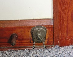
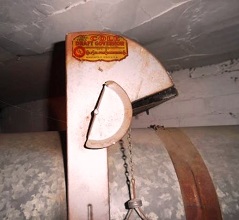
From left to right: Figure 7: Gravity Heat Control; Figure 8: Air Supply, Cole Draft Governor
Turning this “thermostat” open supplied more air to the fire, increasing the heat supplied to the boiler water. Hotter water naturally circulated upward through the system, and the temperature rose inside the home. When the “thermostat” was turned down, less air was supplied to the fire, resulting in lower temperature.
Later, damper controls were automated with a temperature-sensing element. We set the thermostat to a given temperature. A temperature change from the set point would activate a small motor to open or close the air supply damper(s).
How Boiler Expansion Tanks Evolved
With the pre-1930 gravity systems, it was essential to keep the system full of water. An expansion tank was located in the attic (See Figure 9: Expansion Tank in Attic). The tank was open to the air (See Figure 10: Hydronic Boiler Expansion Tanks) with a drain line down to the basement drain or to a visible location outside. If the system overflowed, the homeowner would notice the water. On the other hand, if there wasn’t enough water in the system, upper parts of the home turned cold.
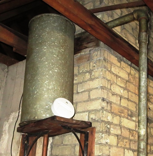
Figure 9: Expansion Tank in Attic
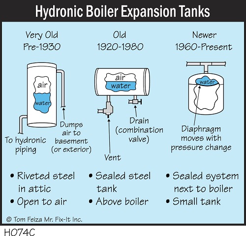
Figure 10: Hydronic Boiler Expansion Tanks
Pre-1980 furnaces incorporated a galvanized steel tank in the floor joists above the boiler. Then came the modern systems (1960-present), which use a much smaller expansion tank placed next to the boiler. The tank incorporates a diaphragm or rubber bladder that separates the water from the air. Keeping them separate prevents water from depleting the air cushion. Modern systems also have an air eliminator to remove air from the system when necessary.
The old gravity systems were monitored as they were filled manually. Modern closed systems are also manually filled, but from then on they are automatically maintained with water supplied from a pressure-reducing valve. A backflow preventer separates the boiler water from the potable water system.
Delivering Balanced Heat
In the old gravity systems, piping size and layout were critical to delivering the right amount of heated water to radiators in each room. Imagine the steamfitter installing a system. It had to be a perfect layout, and the large iron pipes had to be threaded and screwed together. Today we use multiple pumps, zone control valves, and separate thermostats to ensure balanced heat delivery.
The old radiators were manufactured in different sizes. Adding or removing sections from the radiator controlled heat delivery– a wider, taller radiator delivered more heat. These “radiators” actually heated the room through conduction, convection and radiation. Warm water transferred heat to the metal radiator through conduction. The warm cast iron radiated heat to cooler surrounding surfaces, such as our skin. The air around the radiator was heated through convection – warmed air flowed across the cast iron and drew cold air off the floor to the base of the radiator. The rising warm air circulated over the cold windows and around the room.
What We See Today
Most of the gravity boiler systems are gone. Coal delivery is being phased out all over the country. These gravity systems were inefficient, and modifying them is difficult and expensive. Modern homeowners also demand better temperature control than they could deliver.
Despite those changes, you might see remnants of the old systems and now you can identify them for your customers. I often find the old chain-linked “thermostats” and abandoned attic expansion tanks. Vent connectors installed through basement walls are often visible but blocked off.
The best clues to an old gravity hydronic system are the old cast iron radiators and large piping. When you see a more modern boiler with a circulating pump, look at the pipe sizing. You will find a one-inch pipe at the pump and boiler, as well as fittings to the old four-six-inch pipe.
A final tip: the old radiators are not compatible with modern Fin Tube Heating or in-floor heating. These systems operate at much different temperatures. If you see a boiler connected to a mixture of hydronic heating devices, there should be controls and heat exchangers to modify the water temperature.
Free Risk Management Online Course Claims and Complaints: How to Stay Out of Trouble
Available Now
Presenter: David Brauner, Senior Insurance Broker OREP
David Brauner, Senior Broker at OREP, shares insights and advice gained over 25+ years of providing E&O insurance for inspectors, showing you how to protect yourself and your business. Watch Now!
About the Author
Tom Feiza has been a professional home inspector since 1992 and has a degree in engineering. He has inspected more than 9,000 homes. Copyright © 2019 by Tom Feiza, Mr. Fix-It, Inc. Visit HowToOperateYourHome.com (or htoyh.com) for more information about building science, books, articles, marketing, homeowner tips, and illustrations for home inspectors. Tom helps professional inspectors help their customers and boost their business. E-mail Tom (Tom@htoyh.com) with questions and comments, or phone (262) 303-4884. Tom also provides educational presentations for home inspector events.
Note: The Summer 2019 issue of Working RE Inspector is mailing now to over 20,000 home inspectors nationwide. OREP Insureds enjoy guaranteed delivery of each print magazine and many more benefits.


by Michael Ford, AGA, SCGREA, GAA, RAA, Realtor®
What a great, and interesting article!. Thank you. My only experience as an appraiser with a hydronic system was early in my career on Whitley Terrance in Los Angeles. Famous architect-designed slate flooring inside the house and brick patio around the pool. Both heated by over 1/4 mile of copper tube hydronic system under the surface. Same boilers you show were in the partial basement. Your article was both informative and nostalgic for me.
-