

 | > E&O/GL Insurance for Home Inspectors Competitive Rates, Broad Coverage, Free Risk Management, online inspection support for tough questions, discounts on education and more… Professional Coverage, Competitive Pricing Shop OREP today! |
The Inconvenient Truth About Three-Light Receptacle Testers
by Mike Twitty
I promise to tell the truth, the whole truth, and nothing but the truth…unless I’m wrong.
Most home inspectors are familiar with three-light receptacle testers. They are typically standard equipment in an inspector’s tool bag. It is understandable why these testers are so popular. They are inexpensive, small enough to fit in a shirt pocket, and give instant results. This makes them very convenient to use. However, there is also an inconvenient truth to them. The inconvenient truth is that they have many limitations and are often inaccurate.
Many different manufacturers make receptacle testers. They all basically use the same technology and three lights to show proper/improper installations. These are designed for testing 120-volt receptacles. Some have more features than others, such as a test button for evaluation of GFCI protection.
How Do Three-Light Receptacle Testers Work?
The design is pretty basic among receptacle testers, but unfortunately can give false information.
The left side light will illuminate when there is a voltage between the neutral slot on the receptacle and the ground slot. This shows reversed polarity and must have a ground reference to reveal this defect. The center light illuminates when there is voltage between the neutral slot and the hot slot. No ground reference is needed but the polarity could be correct or reversed and the tester would show the same. The light on the right side illuminates when there is a voltage between the hot slot and the ground slot. So, when the center and right side lights are illuminated, the tester indicates that the wiring is correct and working properly. However, when the center and left side lights are illuminated, the tester shows reversed polarity. When only the center light is illuminated, the tester indicates an open ground and a voltage between the hot and neutral slots but does not confirm proper polarity (See Figure 1: Three-Light Receptacle Testers).
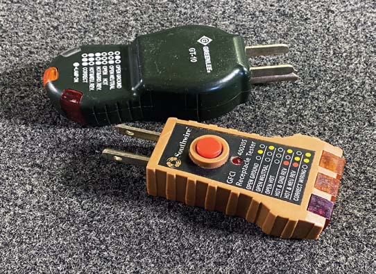
Figure 1: Three-Light Receptacle Testers. (Note: Some testers may use different positions for the indicator lights than the examples above.)
False Readings
False readings are common on three-light testers. Bootleg grounds will fool the tester. The bootleg jumper connects the neutral and ground slots in the receptacle and allows a voltage from the hot slot to both the neutral and ground slots and shows correct wiring (See Figure 2). Another false reading can be the “hot/ground reversed” indication. While that could happen, the more common cause of that reading is an open neutral to the receptacle and a lamp or other device is plugged into the receptacle or a downstream receptacle. The power feeds through the plugged-in device from the hot slot to the neutral slot, energizing both with equal voltage. The tester sees a voltage from the hot slot to the ground slot and from the neutral slot to the ground slot and illuminates the two outside lights. The center light is off because there is no voltage between the hot/neutral receptacle slots.
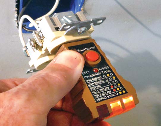
Figure 2: Bootleg ground showing correct wiring. (Note: The jumper wire from the grounding screw to the neutral screw.)

(story continues)
Inaccurate Legend Information
The legend information on three-light testers is sometimes inaccurate and incomplete. At best, they can give an indication that something is wrong, and in some situations, they will not even do that. Never rely on these testers for confirmation to safely work on electrical equipment. For example, no lights do not necessarily mean that the receptacle is not still energized. A dangerous condition is when a bootleg grounded receptacle has reversed polarity (See Figure 3). This condition will energize the metal yoke of the receptacle and the metal chassis or frame of anything plugged into it, while the tester shows “correct wiring.” Refer to Figure 4 for a Standard Tester legend and see Figures 5 and 6 for Multiple Possible Conditions and Other Conditions not listed on the legend.
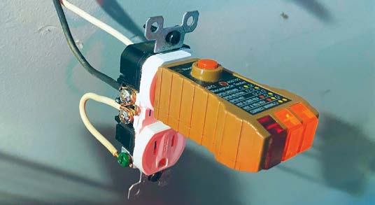
Figure 3: Dangerous reversed polarity bootleg grounded receptacle, showing correct wiring. The metal yoke of the receptacle is energized at 120 volts.
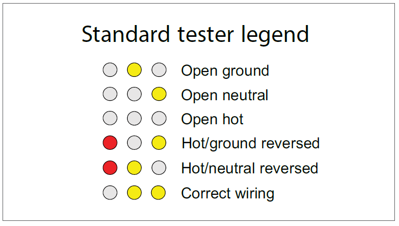
Figure 4: Standard Tester Legend
Sometimes, one of the lights may be dimmer than the others. This usually indicates a loose or bad connection. Another dangerous condition that sometimes occurs is when a 240-volt supply is connected to a standard duplex receptacle. The tester will illuminate all three lights when plugged into this receptacle. The center light will be brighter because the voltage to it is 240 volts.
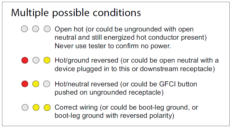
Figure 5: Multiple Possible Conditions
GFCI function on a three-light tester
The test button on the tester shunts the hot slot to the ground slot through an internal resistor to simulate a ground fault. In a properly wired and grounded receptacle, this test will trip the GFCI protective device. However, if the receptacle is not grounded, the tester will show reversed polarity when the button is pushed, even if the polarity is correct. Then, since there is no ground, the button will not trip the GFCI. The test button on the GFCI device will trip the device even when no ground wire is present. This is why testing with the GFCI device’s built-in test button is preferred (See Figure 7).
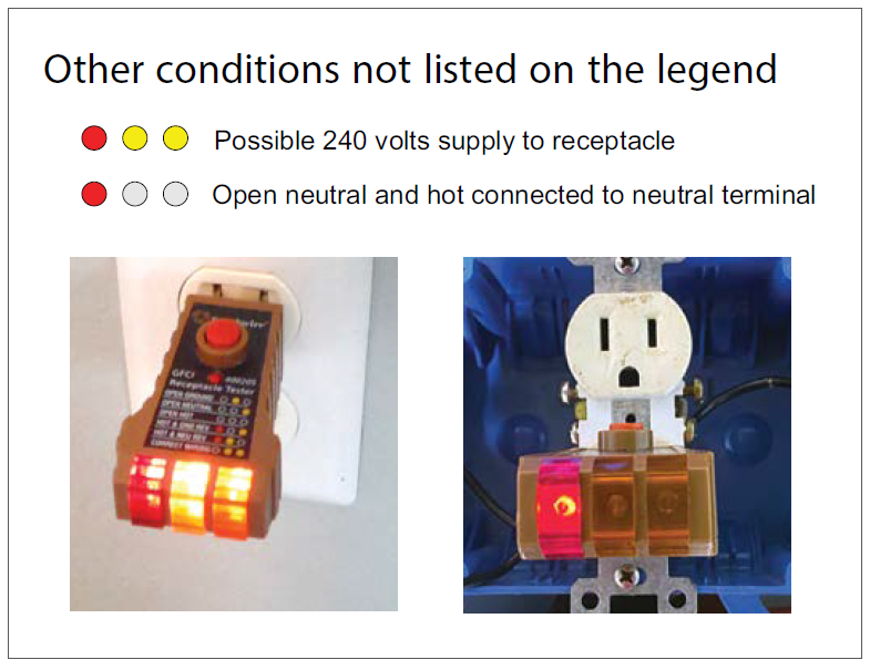
Figure 6: Other Conditions Not Listed on the Legend
Summary
We have gone into a good amount of detail discussing these testers. This is because a three-light tester is probably the most used electrical test device in a home inspector’s tool bag. They are handy and can be useful in electrical inspections. It is important, however, for inspectors to understand the limitations of these testers. They can give false and/or incomplete information.
Figure 7: Ungrounded receptacle showing reversed polarity when the GFCI test button is pushed.
Multi-meters and circuit analyzers can be a better choice in evaluating receptacle wiring, particularly when there is evidence of unprofessional installations. Considering all available conditions can assist the inspector in making evaluations as well. Often, there are clues to alert the inspector that more accurate testing procedures or further evaluations are necessary. For example, in an older home with (apparently) grounded receptacles, always closely review the electrical panels for equipment grounding conductors. If none or very few are present, some bootlegging could be going on.
About the Author
Mike Twitty retired from a 17-year home inspection career in 2021. He is a licensed electrician and an ICC certified electrical code compliance inspector for residential and commercial installations. Mike currently stays busy providing continuing education for home inspectors focusing specifically on electrical subjects. He can be reached via email at: mtwitty2@hotmail.com.
OREP Insurance Services, LLC. Calif. License #0K99465
by W Kading
Well now your going beyond standards of practice, invasive inspection.
-